Training Schedule
Training for Infrared and EMT professionals world-wide.

Welcome back! This month we continue our discussion on Rotor and Stator Analysis Using Current Signature. Please click here for Part One.
If we have a motor that the rotor speed is 1740 RPM, the synchronous rotating magnetic field is 1800 RPM. To determine the number of poles, you divide 7200 by the synchronous speed. The synchronous and actual rotor speeds must be converted to Hertz. The difference is multiplied by the number of poles.
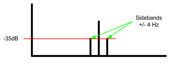
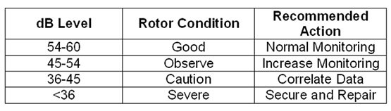
The noise or dB level of these sidebands is indicative of the severity of the rotor fault. When a dB value of < -35 dB is noted, immediate action should be taken.
As the rotor fault progresses, more bars open, slip frequency increases, load increases and the dB level of the Fpp sidebands get lower (closer to zero baseline.) It should also be noted that many normal conditions, such as rotor type and design can give similar indications. Because of this, it is prudent to check for additional correlation. The easiest to check, at this point, is for rotor harmonics, otherwise referred to as the “swirl effect.” This will result in 3 peaks just below the 5th harmonic or 300Hz.
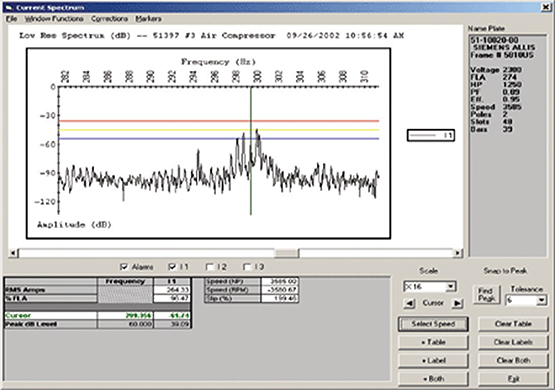
The image at right displays the “Swirl effect” caused by rotor harmonics. In addition to the above discussed methods, other confirmation or data correlation is possible to confirm broken rotor bars.
Please join us again next month for Part Three of Rotor and Stator Analysis Using Current Signature. We will continue our discussion on distortion, slip frequency, swirl effect, and using Motor Current Analysis for confirming rotor bar faults.


