Training Schedule
Training for Infrared and EMT professionals world-wide.

Welcome back! We’ll continue our discussion on Rotor and Stator Analysis Using Current Signature. Let’s review what we have examined so far:
The last test that can be employed is monitoring in-rush current during a motor start. It’s best if a baseline test or even several in-rush test have been taken previously for comparison.
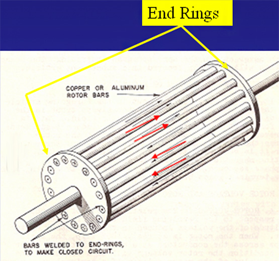
First we need to discuss the rotor as an electrical circuit. The rotor circuit is comprised of rotor bars that are copper or cast aluminum that run the length of the rotor. They connect at either end to shorting or end rings. When the magnetic field in the stator cuts through the rotor bars a voltage is created and current flows through the bars. The equivalent circuit for these rotor bars would be like many resistors in parallel. Each bar would represent a parallel resistance. If one or more of these bars is opened the circuit resistance increases which means the overall impedance of the rotor increases. With a higher rotor impedance, a reduced current would be noted when monitoring in-rush current and comparing it to baseline data. Because of this increased rotor impedance torque will be reduced and it will take longer than normal for the rotor to get up to operating speed.
So, specifically what we are looking for correlation or confirmation during starting of a motor with suspect rotor bar faults, is decreased starting current and a longer transition to run. This is displayed in the image below. The baseline in-rush current was 70 amps with a 1 second transition to run speed.
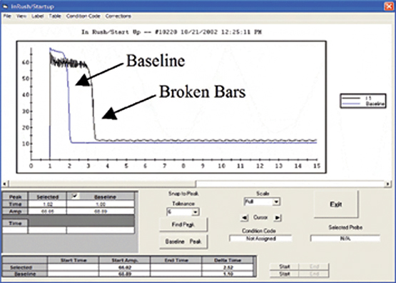
The subsequent test with broken rotor bars displayed 65 amps and almost 1.25 seconds longer to transition to run.
Now the final review:
Distortion in the current time domain waveform.
The presence of Fpp sidebands at the slip frequency of the rotor.
Decreased in-rush or starting current.
Increased transition to run time.
Motor current signature analysis is the optimum technology to identify and confirm rotor bar faults. It will identify these faults long before other technologies and provide correlative data to confirm initial indications. For more information on Electric Motor Testing, consider attending one of Snell Group’s 32hr formal training courses.


