Training Schedule
Training for Infrared and EMT professionals world-wide.

In the maintenance and reliability world, there is a plethora of diagnostic technologies available with ever increasing capabilities. Vibration, oil, ultrasound, infrared, motor circuit analysis, electrical and current signature analysis, for examples, all have a wide range of capabilities that overlap with the capabilities of the other technologies. Each technology has its own unique characteristics that make it better than the others for particular areas of analysis. With the case of Motor Current Analysis that particular area of capability is for identifying rotor and stator anomalies.
In my experience over the past two decades, I have routinely found rotor anomalies developing a year or more before other technologies were able to identify them. Not only that, but I have been able to correlate other load current data and make a definitive diagnosis. Why is this possible? How can monitoring current provide such an early warning and self-confirming diagnosis? In this article we will explain the process and explore the methods of current analysis and correlation.
So what is motor current analysis? It entails evaluation of the load current in both a “Time Domain,” and in a “FFT or Fast Fourier Transform.” Use of both is essential to proper analysis.
Let’s use broken rotor bars as a example.
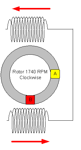
The image above shows one set of stator field poles and the rotor. The rectangle at 3 o’clock represents broken rotor bars (A). As the rotor turns in the clockwise direction the anomalous area of the rotor will pass through the magnetic field created in the stator field pole at 6 o’clock(B). The area of the rotor with broken bars will not have any current flow in the bars and therefore no magnet field around the bars. This will cause a momentary loss of torque as it passes the field pole and a corresponding pulse in in the phase current for that pole. Since the poles in the stator are connected it will be sensed by both poles in that phase at the frequency of the rotor anomaly passing the poles, also referred to as “field pole pass frequency or Fpp.” The pulse created will have an effect on current and can be seen in both the “Time Domain” and “Frequency Domain.”
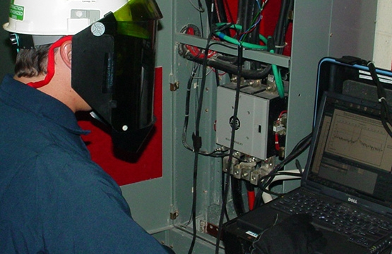
The first indication of a developing rotor problem would likely be noticed by an operator. The motor will be drawing higher current than it would normally for the same process. This is when a motor analyst should be called in to perform diagnostic testing.
A normal testing sequence would entail a power quality test first. This will determine if the motor has balanced and proper voltage. Low or unbalance voltage could give similar loading indications. Once it is determined that we have balanced voltage and current, we are going to look at the current time domain.
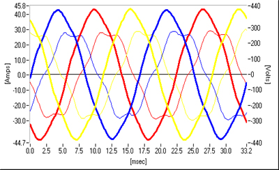
Because there is no current flow in the broken rotor bars there is no magnetic field around the bars and no interaction with the stator magnetic field. This magnet distortion will be visible in the current wave form and cause more distortion as the rotor condition deteriorates. The momentary loss of torque and the resultant Fpp sidebands will show in the frequency domain.
Since the flow of current in the field poles in the stator are connected in series, we see 2 pulses one from each field pole. The effect of these pulses will be determined by motor load, the severity of the rotor condition and the RPM.
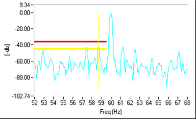
To calculate where the Fpp sidebands should appear you subtract the rotor speed from the synchronous speed of the rotating field in the stator in hertz. The difference is then multiplied by the number of poles. This value is the location of the Fpp above and below line frequency.
Please join us next month for Part Two of Rotor and Stator Analysis Using Current Signature. We will continue our discussion on rotor harmonics, distortion, rotor fault, and monitoring in-rush current during start up.


