Training Schedule
Training for Infrared and EMT professionals world-wide.


As the surface being inspected is viewed from larger and larger angles away from perpendicular, the apparent flaw size will decrease. Depending on orientation and/or geometries, these situations must be taken into consideration when creating inspection procedures with maximum allowable flaw sizes. In the sequence of pictures below we have simulated the number of detectors, or pixels, projected on a surface--no allowance has been made for the depth of the flaw. As can be seen, fewer and fewer pixels are actually receiving energy from the flaw as we increase the viewing angle from perpendicular up to 60°.
In this example major and minor dimensions of the flaw in an X-Y orientation are both 5 pixels and the infrared camera detector, lens used and distance to target establish the actual pixel size. But in the series of images below we see a decrease in X axis dimension.
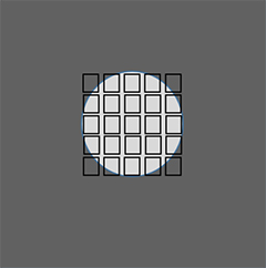
90° or Perpendicular to the Surface
5 pixels in the X axis and 5 pixels in the Y axis.
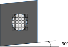
30° Angle
4.3 pixels in the X axis and 5 pixels in the Y.
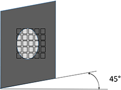
45° Angle
3.5 pixels in the X axis and 5 pixels in the Y.
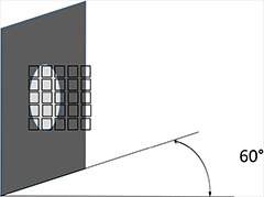
60° Angle
2.5 pixels in the X axis and 5 pixels in the Y.
Inspection orientation must be moved closer to 90° or correction factors must be established and procedures must address the issue. These correction factors are used to establish actual flaw size and in some cases used for variations in depth too. The depth of an anomaly or flaw may affect size measurement even when measuring from near perpendicular. Other things to consider involving angle include the variation of inspection angle across the field of view (FOV) and the resulting change in emissivity. And if part excitation is being accomplished with a flash or pulse of visible light energy will the angle affect the energy absorbed by the part.
So when testing a standard or known flaw size and it is determined that measurements do not correlate to actual values correction factors should be considered. For difficult applications the use of a reflector to get light energy in and an infrared signal out may be a better option. The procedures for determining and the resultant values of these correction factors should of course be approved by the responsible Level 3.


