Training Schedule
Training for Infrared and EMT professionals world-wide.

Welcome to part II of Common Ground System Configurations. We will continue where we left off in Part I. If you missed Part I, you can find it here: Common Ground System Configurations - Part One
In a high resistance grounding configuration, ground current is typically limited to around 10A. The reason for this is to allow the system to operate without tripping. This sort of configuration is designed to allow machinery to operate in a fault condition for extended periods of time. If applied to rotating machinery, this type of configuration can reduce damage to the core iron of the motor. The downside is that the phase voltages will increase on the unfaulted phases, and will remain elevated for extended periods of time. Thus the insulation within the system must be rated for the level of the phase-to-phase voltage. These voltage levels are dependent upon the net capacitive charging current of the fault must be less than that of the resistively controlled ground fault current fed from the Neutral-Earth path. The grounding resistor must also be rated for continuous duty as it will be conducting fault currents for extended periods.
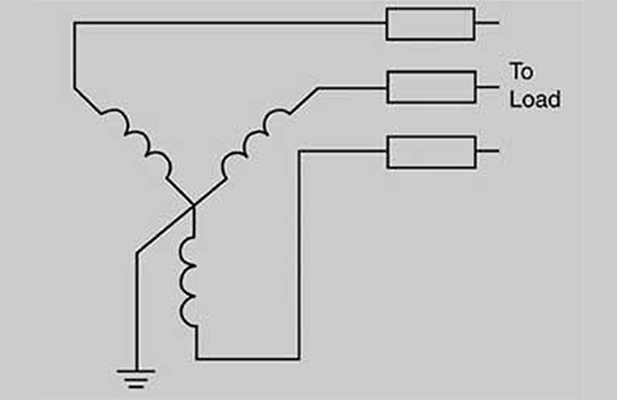
In an ungrounded system, there is no intentional path to Earth ground through a neutral path. This sort of configuration is sometimes called “floating ground” or “floating neutral” systems, because there is no Earth reference point in the system. This configuration is susceptible to substantial transient over-voltages if the ground fault is arcing or intermittent. These transient over-voltages can be 6 to 8 times the phase voltage levels, and often cause failure elsewhere.
Often the application of the various types of grounding configurations depends on factors such as the need for system continuity, or precision of delivered voltage levels. The IEEE Standard 142-2015 (Green Book) specifies the advantages of solidly grounded systems. Among them is increased safety due to the ability of protective devices to isolate faults. Additionally, the reduced risk of over-voltage conditions can enhance component reliability. The downside is the increased exposure to danger from arc flash conditions that are most typically associated with solidly grounded systems.
Conversely, there are also reasons specified in the standard for why limiting ground fault current through the application of resistance may be preferable. One consideration against solidly grounded configurations is the high magnitude of fault currents involved. The energy levels can be high enough to melt insulation and even conductors. Additionally, the level of risk from injury due to an arc flash is increased in a solidly grounded system. Adding resistance to system grounds for the express purpose of reducing fault currents is a relative new concept, and as such are not as apt to be found in older applications.
For many low voltage applications, whether they are in industrial or manufacturing facilities or in commercial properties, grounding is usually either insulated neutral (ungrounded) or solidly grounded. This is not to say that low resistance grounding and high resistance grounding configurations aren’t used in LV applications, but when they are used it is ordinarily designed and implemented for particular equipment requirements.
When utilized in low voltage applications, an ungrounded system will often be accompanied by lamps connected to each phase to indicate a when a ground fault is present. This arrangement serves to indicate the presence of a ground fault, but can’t pinpoint the location. This configuration is common in continuous manufacturing applications due to the ability of the system to operate in a faulted condition. From the standpoint of safety, ungrounded systems present the particular danger of electrocution if contact is made by personnel while a fault condition exists. The ground fault current path offers higher impedance than would a human body that is in contact with Earth ground, and current prefers the path of least resistance.
Do you know what type of distribution and grounding system you have at your facility? Do you know how it may affect your collected motor data? Consider attending Snell Groups Energized Electric Motor Testing Course, a 32-hour formal training class that is presented at various locations for “Open” attendance or can be tailored specifically for presentation at your facility.


