Training Schedule
Training for Infrared and EMT professionals world-wide.

To properly conduct energized electric motor testing for the purpose of gathering voltage and current data, it is important to have a general understanding of the types of grounding systems utilized in commercial and industrial applications. The type of grounding system may have a drastic effect on acquired motor circuit test data. Additionally, the lack of a basic understanding could impede your ability to interpret possible faults.
Despite its importance to the overall functionality of an electrical distribution system, grounding is still mostly misunderstood. Due to this phenomenon, grounding configurations are often misapplied. When this happens, the results can be costly, and in some cases, cause catastrophic failures.
Facilities managers, electrical contractors and even electrical engineers find themselves confounded by ground configuration applications. The motor test technician isn’t alone in his or her confusion when it comes to this misunderstood necessity. Proper operation of many sophisticated electrical instrumentation and control systems, as well as power systems for major equipment systems rely on the proper application of grounds. Just as concise and accurate information about the current delivery circuitry of any facility or system is vital, so is similar data on systems grounds.
For the sake of understanding from a systemic perspective, as well as its importance in motor circuit evaluation, let’s take a look at some common grounding configurations. Each configuration has its pros and cons, and there are some configurations that are designed to be applied in certain circumstances to achieve maximum efficiency and functionality of the system as a whole. Rather than considering grounding as a separate component, it can be beneficial to think of it in terms of its inclusion in the overall system.
Important to remember is that grounding and neutral are not always synonymous terms. Neutral is intended as the return path for unused portions of the phase energies, and in normal operations often carries current. Ground conductors on the other hand are usually not expected to carry current, except in special configurations and applications.
Typically, the greatest variation in grounding systems is seen at the medium voltage system level. Once the system voltage is transformed to 600VAC and below, we typically see less variation. In the medium voltage system level we would see one of four possible configurations.
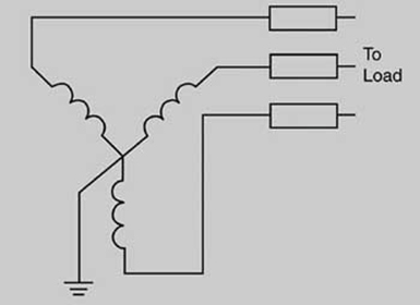
In solidly grounded systems, there is no intentional impedance in the neutral path to Earth. This allows for phase to ground voltage to remain constant in a fault condition, which in turn creates great magnitudes of fault current. To prevent damage to conductors, the protective device closest to the fault must clear very rapidly to isolate the fault. If the fault is in a circuit powering rotating machinery, a single phase condition can result causing core damage to the motor.
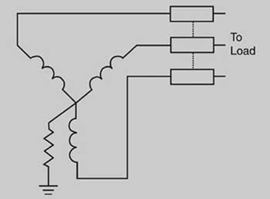
In low resistance grounding systems, in a fault condition the fault current is limited by impedance in the Neutral-Earth grounding path. This allows for more controlled protective device coordination, but the tradeoff is the probability of over voltage conditions developing on the un-faulted phases in a fault condition. The resistor used in the ground circuit has to be time rated in order to not clear before the protective relay for the circuit.
Watch for next month’s EMT newsletter where we will continue with Part Two of "Common Ground System Configurations".


